Installation and integration
Depending on the length of the CIS scanner, a different number of Camera Link cards is required.
Without a working Camera Link connection, integration in EasySightPro® is not possible.
Information: To integrate the scanner, the additional component "Mitsubishi CIS Driver" must be installed.
Install the cards in a suitable PCI Express slot. If more than one card is used, then the card number must be set by means of a DIP switch.
| Number (VALUE) | DIP 1 | DIP 2 | |
|---|---|---|---|
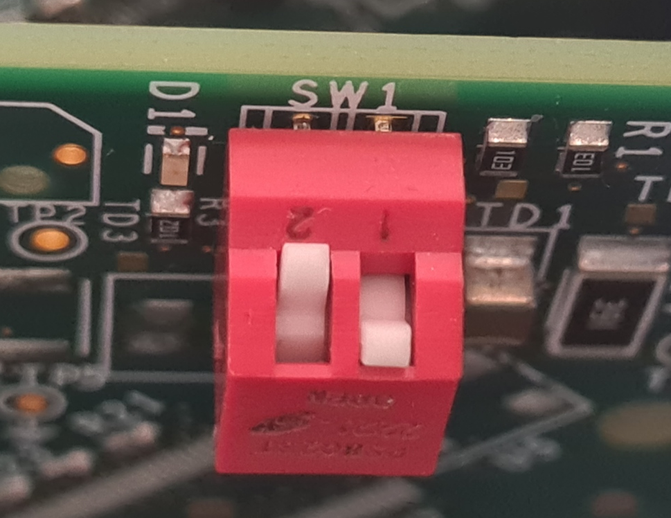
|
0 | 0 | 0 |
| 1 | 1 | 0 | |
| 2 | 0 | 1 | |
| 3 | 1 | 1 | |
The cabling of each Scanner Module is done to the corresponding Camera Link card.
| Scanner | Camera Link card | |
|---|---|---|
| CN12 | BASE | 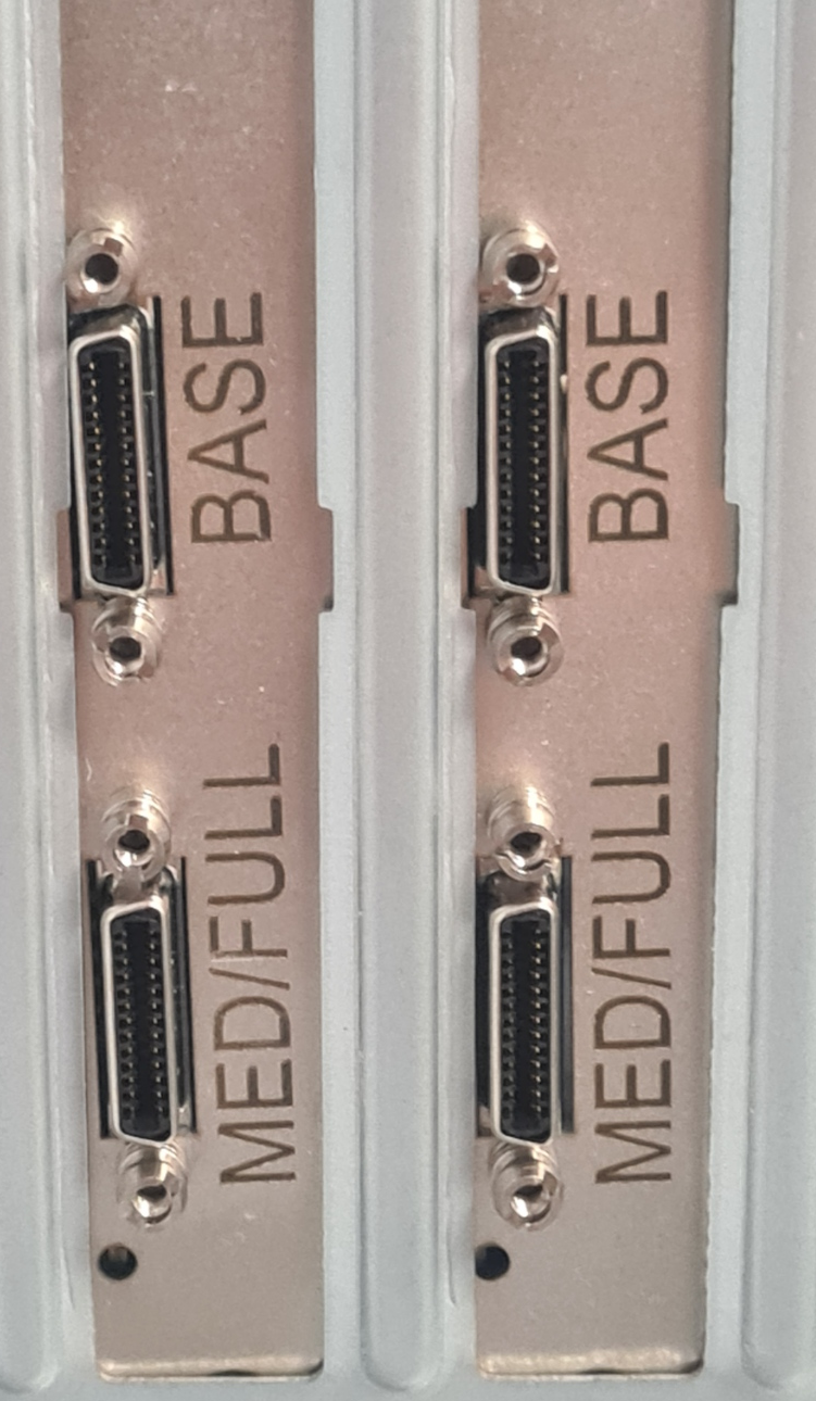
|
| CN13 | MEDIUM | |
The digital I/Os are synchronized via the master interface. The communication module is located at a different place depending on the CIS type. Please check in the manual.
When wiring the scanner, make sure that the voltage levels of the individual connectors are correct, as the device will be damaged if the wiring is incorrect. The installation instructions according to the manufacturer must be observed!
| Connector | Voltage |
|---|---|
| CN11 | +5VDC ±0,1V |
| CN91 | +24VDC ±0,5V |
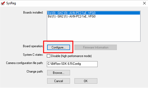
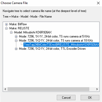
After successful installation, the corresponding configuration file is assigned to each Camera Link card:
|
1. Start Sysreg |

|
|
2.0 Configure each card |
|
|
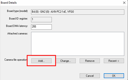
2.1 Add configuration to card |
|
|
2.2 Choose mode: "TS runs camera at 5 kHz": Fixed line rate of 5kHz (for testing purposes with BitFlow Preview) "TS runs camera at 10 kHz": Fixed line rate of 10kHz (for testing purposes with BitFlow Preview) "TTL Encoder Driven": Line rate is specified by TTL rotary encoder (Default for use with EasySightPro®) |
|
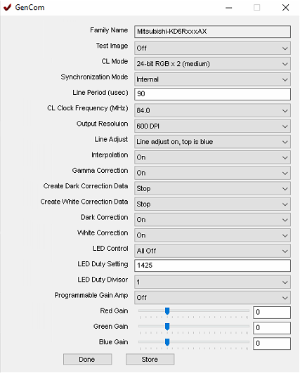
GenCom is a generic tool for parameterizing the CIS scanner. This is not necessary for productive operation, but offers a quick way to test the connection between the card and the scanner.
|
1. Start GenCom from "[EasySightPro Setup Location]\BitFlow\GenCom" |

|
|
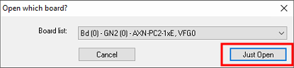
2. Select correct card (master interface) The communication module is located at a different place depending on the CIS type. Please check in the manual. |
|
|
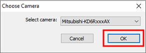
3. Select "Mitsubishi..." configuration |
|
|
4. If the connection can be established, then a window appears with the current scanner settings. |
|
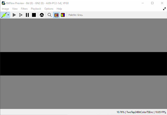
Preview is a tool to test the image transfer via Camera Link.
For the test, it may be necessary to change the operating mode to "free running" using sysreg (in case the image transmission is to be tested without encoder).
|
1. Start Preview |

|
|
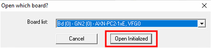
2. Select card |
|
|
3. If the connection can be established, then a window appears with the current playback. In the event of an error, check the correct Camera Link cabling! |
|
If all connection tests have been completed positively, then the further integration of the scanner in EasySightPro®.
Up to 4 scanners or a maximum of 4 modules per controller are supported.
|
This module is subject to a fee and is not included in the standard scope of delivery |
|
|
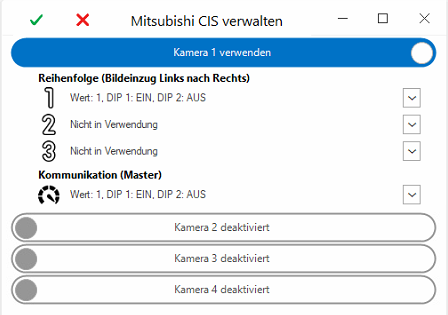
2. Merge Camera Link cards into one scanner This is done via the Mitsubishi CIS administration under "Administration - Mitsubishi ". |

|
|
3. Configure scanner The assignment is done via the DIP switch number (value) of the Camera Link card. In the case of a scanner with several modules, the sequence can be used to configure the assembly of the modules to form the overall image. |
|
|
4. Scanner can now be used as a camera in the administration. |